
Introduction
If you are creating fun and attractive Web application with animations, graphic and different attractive and fun services, then sometimes you need user to create images online. For example to post it on the page of another user or something like this. This article describes control, that you can use for such purposes. This control is Silverlight 4 based.My original article with sources to download: http://www.codeproject.com/KB/silverlight/imageeditor.aspx
Application overview
As I said before, this application in attachments contains control, that allow web user to create simple images online. This control doesnt create any JPEG'g or PNGs, but it returns ImageSource to developer, and developer can use this ImageSource for his purposes: create images, backgrounds, etc.There are following tools and features:
- Round brush
- Size of brush
- Color of brush
- Brush opacity
- Clear and undo features
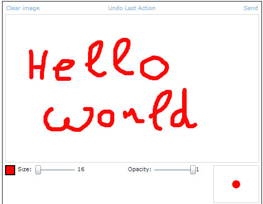
At the top there are Undo and Clear command buttons. Middle is a canvas with image. At the bottom there is color, size, opacity and brush preview.
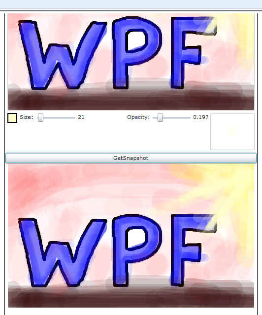
Also, in the application there is button "Get Snapshot" that demonstrate feature that convert drawn image to ImageSource. There is Border at the bottom, which background is that ImageSource. The example of such preview is below:
How to use
This control has following public properties and methods that can be used outside:- BrushColor - dependency property. Brush color
- BrushSize - dependency property. Brush size
- BrushAlpha - dependency property. Brush opacity
- Clear() -clear canvas
- HideTools() -hide bottom tools
- ShowTools() - show bottom tools
- Undo() - undo if available
- GetImage() -get current image
HideTools() and ShowTools() use animations that are defined in related XAML file.
Code
Lets look into sources.The first I wanna describe how image is drawn. There are 3 layers:
<Grid x:Name="Sheet" Background="White" SizeChanged="Sheet_SizeChanged">
                    <Grid.Clip>
                        <RectangleGeometry />
                    </Grid.Clip>
                </Grid>

                <Canvas x:Name="CursorCanvas" Background="Transparent" Cursor="None">
                    <Ellipse x:Name="Cursor" Canvas.ZIndex="100" Visibility="Collapsed"
                                 Opacity="{Binding BrushAlpha}" Width="{Binding BrushSize}" Height="{Binding BrushSize}">
                        <Ellipse.Fill>
                            <SolidColorBrush Color="{Binding BrushColor}" />
                        </Ellipse.Fill>
                    </Ellipse>
                    <Path Stroke="Black" Canvas.ZIndex="101" StrokeThickness="1" x:Name="Cross"
                          VerticalAlignment="Center" HorizontalAlignment="Center" Visibility="{Binding ElementName=Cursor, Path=Visibility}">
                        <Path.Data>
                            <GeometryGroup>
                                <LineGeometry StartPoint="3,0" EndPoint="8,0"/>
                                <LineGeometry StartPoint="-3,0" EndPoint="-8,0"/>
                                <LineGeometry StartPoint="0,3" EndPoint="0,8"/>
                                <LineGeometry StartPoint="0,-3" EndPoint="0,-8"/>
                            </GeometryGroup>
                        </Path.Data>
                    </Path>
                </Canvas>

                <Canvas x:Name="InputCanvas" Background="Transparent" Cursor="None"
                        MouseLeftButtonDown="InputCanvas_MouseLeftButtonDown"
                        MouseLeftButtonUp="InputCanvas_MouseLeftButtonUp" MouseEnter="InputCanvas_MouseEnter"
                        MouseMove="InputCanvas_MouseMove" MouseLeave="InputCanvas_MouseLeave">
                </Canvas>
Sheet - it is a grid that contains geometries that has been drawn.CursorCanvas - contains brush cursor and cross cursor
InputCanvas - collects all mouse inputs. We need it, because otherwise mouse will be always on the Ellipse (brush cursor) that is inside CursorCanvas and there will no MouseEnters and MouseLeave and MouseMove events.
When user press left button, following code is performed:
InputCanvas.CaptureMouse();

            geometry = new GeometryGroup();
            geometry.FillRule = FillRule.Nonzero;
            figure = new Path();
            figure.Fill = new SolidColorBrush(BrushColor) { Opacity = BrushAlpha };
            Sheet.Children.Add(figure);
First, we need to capture mouse, to avoid drawing to be finished after user move out of the control. Next, we create path with selected color and opacity and drop it into Sheet. Geometry variable contains geometry that is drawn right now.When user moves mouse, then Ellipses are added to locations where "MouseMove" event occurs. Ellipses are connected by rectangles. I call this rectangles "connectors". Idea is explained in the image below:
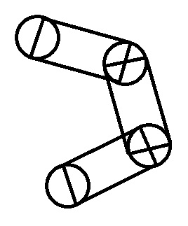
To draw that rectangle I have to know size of ellipses and it's center coords. And I know it. So, it it easy. Following code draws one connector between 2 ellipses:
Point a, b, c, d;
            double x1 = mousePosition.X;
            double y1 = mousePosition.Y;
            double x2 = prevMousePosition.Value.X;
            double y2 = prevMousePosition.Value.Y;
            double l = BrushSize / 2;

            PathGeometry conntector = new PathGeometry();
            conntector.FillRule = FillRule.Nonzero;

            double alpha = Math.Atan2(y2 - y1, x2 - x1);
            double beta = Math.PI / 2 - alpha;

            a = new Point(x1 - l * Math.Cos(beta), y1 + l * Math.Sin(beta));
            b = new Point(x2 - l * Math.Cos(beta), y2 + l * Math.Sin(beta));
            c = new Point(x2 + l * Math.Cos(beta), y2 - l * Math.Sin(beta));
            d = new Point(x1 + l * Math.Cos(beta), y1 - l * Math.Sin(beta));

            PointCollection points = new PointCollection();
            points.Add(d);
            points.Add(c);
            points.Add(b);
            conntector.Figures.Add(new PathFigure()
            {
                IsClosed = true,
                IsFilled = true,
                StartPoint = a,
                Segments = { new PolyLineSegment() { Points = points } }
            });
variables a,b,c,d - are vertices of the rectangle that describe connector. And here is one important thing. I waste some time because of it. This important thing is an order of points.Add() commands. For correct geometry filling you have to add point in counterclockwise order! Otherwise filling will works like you use EvenOdd fill method, even if you choose NonZero.
Ok, what we have? Path that contains set of ellipses and connectors. User release left button and we need to process this data. Most easy way is easily remain this Path in the Sheet and draw next figures. But, some users like to draw very complicate images :) So, if there will be a lot of geometry you can get slowdown. Not good. So, I decided to render this Path and set rendered image as a Background of the Sheet. And it shows me good results. No slowdown.
Following method is called when user release leftbutton:
private void EndFigure()
        {
            mouseLeftButton = false;
            InputCanvas.ReleaseMouseCapture();
            prevMousePosition = null;

            Sheet.Background = new ImageBrush() { ImageSource = ConvertToImage() };
            Sheet.Children.Clear();
        }
ConvertToImage() is a method that convert current look of Sheet into ImageSource. It also used in GetImage() method and I wouldnt return to it's descriptions in the future. So, here it is:
private ImageSource ConvertToImage()
        {
            WriteableBitmap bitmap = new WriteableBitmap(Sheet, new TranslateTransform());
            bitmap.Render(Sheet, new TranslateTransform());

            return bitmap;
        }
Rather easy. Isnt it?
Another thing that I would like to show you - is a color picker. In the app it looks like:
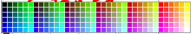
I want to show you algorythm that builds such palette.
int x,y, count;
                x = y = count = 0;

                for (int r = 0; r <= 255; r += 51)
                {
                    for (int g = 0; g <= 255; g += 51)
                    {
                        for (int b = 0; b <= 255; b += 51)
                        {
                            Border brd = new Border()
                            {
                                Background = new SolidColorBrush(Color.FromArgb(255, (byte)r, (byte)g, (byte)b)),
                                BorderThickness = new Thickness(0),
                                Margin = new Thickness(1),
                                Width = 15,
                                Height = 15,
                                Cursor = Cursors.Hand
                            };
                            brd.MouseLeftButtonDown += delegate
                            {
                                SelectedColor = ((SolidColorBrush)brd.Background).Color;
                                ppColors.IsOpen = false;
                            };
                            count++;
                            cnvColors.Children.Add(brd);
                            Canvas.SetLeft(brd, x);
                            Canvas.SetTop(brd, y);
                            if (count >= 6)
                            {
                                y = 0;
                                x += 17;
                                count = 0;
                            }
                            else
                            {
                                y += 17;
                            }
                        }
                    }
                }
The idea is to go through all possible sets of R and G and B values and add border with such RGB to container. Since R,G and B are bytes, their max is 255. So, total count of colors will be 255*255*255 = 16581375....Heh, too much :) So, lets reduce number of steps: and increase component values with 51 instead of 1. So, for one color component we will have only 255/51=5 values.
Total number of colors is 5*5*5 = 125. It's ok for this application. To make palette looks nice I choose offset values, that the same colors was in the same column and in the same row.
Results
In this application, I tried to create easy to use and easy to modify control, that allows you to create simple image editor in your application. You can use it as-is, or re-use only some parts of it: for example ColorPicker.Also, here you can get some interesting information about working with geometries, mouse capturing and oprimization by rendering a lot of controls into image.
No comments:
Post a Comment